
When undertaking a motor control project, the first step is often not motor selection, but defining the drive solution. Many novice developers fall into a common pitfall: they finalize the motor first, only to end up with an incompatible driver IC. Issues include insufficient power to drive the motor, over-specified functions that drive up costs, or mismatched control schemes making tuning impossible.
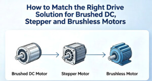
Brushed DC, stepper and brushless motors are the three most common types. They operate on fundamentally different principles and require completely distinct drive solutions. Today, we break down the drive logic, key selection criteria and typical solutions for these three motor categories in one comprehensive guide, helping you quickly identify a matching drive scheme.
First, Understand the Core Differences Between the Three Motor Types
Variations in drive solutions stem from the motors themselves.
Brushed DC Motor: The Simplest, Most Traditional Option
It relies on brushes and a commutator for mechanical commutation. Applying forward voltage yields forward rotation, reverse voltage yields reverse rotation, and speed is adjusted by varying voltage.
Advantages: Low cost, high starting torque, simple control.
Disadvantages: Brush wear limits service life; electrical spark interference occurs during operation.
Stepper Motor: Rotates in Discrete Steps
It turns by fixed angular increments. Rotational position is controlled by pulse count, while rotational speed is governed by pulse frequency.
Advantages: High positioning accuracy; position control achievable in open-loop configuration.
Disadvantages: Severe vibration at low speeds, rapid torque drop-off at high speeds, risk of lost steps.
Brushless Motor (BLDC/PMSM): High Performance with Complex Control
Electronic commutation replaces mechanical brushes. The driver IC rotates the motor by sequentially energizing the three-phase windings.
Advantages: High efficiency, long service life, low noise, wide speed range.
Disadvantages: Complex control requiring dedicated drivers and algorithms.
Stepper Motor Drive Solutions
Stepper motors are widely adopted in 3D printers, CNC machine tools, automation equipment and medical instruments, with an extensive range of available drive solutions.
Microstepping Drive as Standard Configuration
The core feature of stepper drives is microstepping — splitting one full step into numerous smaller steps to deliver smoother motion, lower noise and finer positioning. Early stepper drivers only supported full-step and half-step operation. Nowadays, 256 microstepping has become mainstream, and high-end ICs support even higher microstep resolution.
Power Rating Selection Based on Phase Current and Supply Voltage
The two most critical parameters for stepper drive selection are phase current and supply voltage:
Low power (1~2 A): Select compact integrated drivers
Medium power (2~4 A): Select medium-current drivers
High power (8~10 A and above): Adopt high-current drivers or solutions with external MOSFETs
Note: The rated current of the driver IC should be 1.2~1.5 times the motor’s rated current to provide adequate safety margin, preventing overheating and reliability failures under prolonged full-load operation. The same principle applies to supply voltage; ICs supporting a wide voltage range offer greater flexibility for matching different motors later on.
Advanced Option: Drives with Integrated Motion Controllers
Conventional stepper drivers require the MCU to continuously output pulse signals to drive motion. This consumes MCU resources, and pulse signals are vulnerable to interference, resulting in lost steps. For smarter, more hassle-free operation, developers may choose driver ICs embedding a motion controller.
Brushless Motor Drive Solutions
Thanks to high efficiency, long lifespan and low acoustic noise, brushless motors see growing adoption in drones, power tools, fans, water pumps, servo systems and new energy vehicles. However, their drive schemes are the most complex among the three categories.
Two Main Control Modes
Square-wave drive (6-step commutation)
Relatively simple to implement with low cost. Suitable for applications with relaxed noise and efficiency requirements, such as general fans, water pumps and entry-level power tools.
Drawbacks: High torque ripple, uneven operation and noticeable noise.
FOC drive (Field-Oriented Control, also known as vector control)
It precisely regulates the magnitude and orientation of the motor’s magnetic field to achieve smooth, efficient and quiet operation.
Advantages: Steady torque, high efficiency, excellent low-speed performance and low noise.
Drawbacks: Sophisticated algorithms that demand high processing capability from the controller.
Nowadays, FOC is widely deployed in mid-to-high-end brushless motor applications. Advances in semiconductor IC technology have gradually reduced FOC implementation costs, prompting a shift from square-wave control to FOC across a growing number of mid-tier applications.
Two Primary Hardware Architectures
Architecture 1: Pre-driver IC + external MOSFETs
The driver IC only outputs gate drive signals, while power MOSFETs are implemented externally. This design enables flexible power scaling and simplifies thermal management.
Architecture 2: Dedicated FOC controller + pre-driver / power stage
Choose dedicated FOC controller ICs if high-performance FOC is required without developing complex FOC algorithms from scratch.
Brushed DC Motor Drive Solutions
Though considered conventional, brushed DC motors remain popular for many applications due to simple control, low cost and high starting torque, including small home appliances, toys, automotive electronics and compact transmission equipment.
Brushed DC drive schemes are relatively straightforward, built around an H-bridge circuit. By controlling the on/off state of the four switching transistors within the H-bridge, forward rotation, reverse rotation, electrical braking and speed regulation can be realized.
Low-power applications: Use integrated H-bridge driver ICs, featuring minimal peripheral components, easy development and low cost.
Medium-to-high-power applications: Adopt pre-driver ICs paired with external MOSFETs for higher flexibility and easier thermal design.
Speed regulation is typically implemented via PWM. The average voltage, and hence motor speed, is adjusted by varying the PWM duty cycle. Careful selection of PWM frequency is essential: excessively low frequency causes audible noise and vibration, while overly high frequency increases switching losses and lowers efficiency. Frequencies ranging from several kilohertz to tens of kilohertz are common, and a balanced choice must be made based on practical operating conditions.
Closing Remarks
There is no universal best motor drive solution — only the most suitable one. A qualified solution delivers sufficient power, matching functionality and reasonable cost.
For beginners, it is recommended to start with highly integrated drive modules or ICs to verify basic functionality before carrying out further optimization. For experienced developers, integrated or discrete schemes can be selected flexibly according to project requirements to strike a balance between performance, cost and form factor.
If you are evaluating motor drive solutions or have questions regarding parameter selection for specific part numbers, feel free to contact us. We can provide targeted solution recommendations tailored to your real-world application scenarios.